The Complete Guide to Dimensioning and Tolerancing
Master Precision in Mechanical Drawing and Design
Master the critical skill that separates good designs from great ones.
238 pages11 chaptersMar 8, 2026Technical Drawing
About this book
This comprehensive guide takes you beyond basic dimensioning to show you how to apply professional-grade tolerancing practices that manufacturers actually use. You'll learn to read and create drawings that communicate exactly what you intend, eliminate costly manufacturing surprises, and design products that work reliably in the real world. Whether you're working with traditional limit tolerances or advanced geometric dimensioning and tolerancing (GD&T), this book provides clear explanations, practical examples, and real-world scenarios that show why each decision matters. Discover how to balance precision with manufacturability, understand tolerance stacking, and apply the right tolerance type for each situation. By the end, you'll have the confidence to dimension any mechanical drawing with precision and clarity.
Table of contents
- IntroductionWhy Dimensioning and Tolerancing Matters, The Bridge from Design Intent to Manufacturing Reality, How to Use This BookRead below
- Chapter 1: Fundamentals of DimensioningBasic Dimension Concepts and Terminology, Types of Dimensions: Linear, Angular, and Radial, Proper Placement and Readability of Dimensions, Standards and Best Practices in Dimensioning
- Chapter 2: Understanding TolerancesWhat Tolerances Are and Why They Exist, Bilateral, Unilateral, and Limit Tolerances, Selecting Appropriate Tolerance Values, Understanding Manufacturing Capability and Tolerance Grades
- Chapter 3: Introduction to Geometric Dimensioning and TolerancingWhat is GD&T and When to Use It, GD&T Symbols and Their Meanings, Advantages of GD&T Over Traditional Tolerancing, The GD&T Framework and Hierarchy
- Chapter 4: Datum References and Datum SystemsUnderstanding Datums and Their Purpose, Selecting Functional Datums, Building Effective Datum Reference Frames, Applying Datums to Control Features
- Chapter 5: Form Tolerances: Straightness, Flatness, Circularity, and CylindricityStraightness: Controlling Linear Elements, Flatness: Controlling Planar Surfaces, Circularity: Controlling Circular Features, Cylindricity: Controlling Cylindrical Surfaces
- Chapter 6: Orientation Tolerances: Perpendicularity, Parallelism, and AngularityPerpendicularity: Controlling Right Angles, Parallelism: Controlling Parallel Relationships, Angularity: Controlling Angled Relationships, Practical Applications of Orientation Tolerances
- Chapter 7: Location Tolerances: Position, Concentricity, and SymmetryPosition Tolerance: The Most Powerful GD&T Tool, Concentricity: Controlling Concentric Features, Symmetry: Controlling Symmetrical Features, Real-World Examples of Location Tolerances
- Chapter 8: Runout Tolerances: Circular and Total RunoutCircular Runout: Controlling Rotation About an Axis, Total Runout: Comprehensive Rotational Control, Measuring and Verifying Runout Tolerances, Applications in Rotating Components
- Chapter 9: Profile Tolerances: Line and Surface ProfilesProfile of a Line: Controlling 2D Profiles, Profile of a Surface: Controlling 3D Profiles, Using Profiles for Complex Geometry Control, Profile Tolerance Examples and Applications
- Chapter 10: Tolerance Stacking and Cumulative Error AnalysisUnderstanding Tolerance Stack-Up, Worst-Case Tolerance Analysis, Statistical Tolerance Analysis, Strategies for Managing Tolerance Stacks
- Chapter 11: Practical Application and Real-World ScenariosMaking Tolerance Decisions in Design, Balancing Cost, Quality, and Manufacturability, Case Studies: Common Dimensioning Challenges, Communicating Tolerances Effectively with Manufacturing
- ConclusionKey Takeaways and Next Steps, Continuing Your Dimensioning and Tolerancing Journey
- Glossary of Terms
- Further Reading and Resources
Introduction
Every mechanical drawing tells a story. It describes a part that doesn't yet exist, communicates a designer's intent to someone who may be thousands of miles away, and sets the expectations that determine whether a finished product works or fails. But a drawing without proper dimensioning and tolerancing is like a story with missing words. The meaning gets lost, the manufacturer guesses, and the result is rarely what anyone intended. This book is about making sure that never happens to your drawings.
Dimensioning and tolerancing is one of those skills that looks straightforward on the surface but reveals enormous depth the more you work with it. You can learn the basic symbols and rules in a few hours. Applying them correctly, consistently, and with real manufacturing awareness takes much longer. The gap between knowing the rules and understanding why they exist is exactly where costly mistakes happen. A hole positioned 0.5 mm off its true location might be perfectly acceptable in one assembly and catastrophic in another. The difference lies entirely in how the drawing communicates the requirement.
This guide was built for engineers, designers, and drafters who already have some experience with mechanical drawings and want to move beyond the basics. If you've ever looked at a drawing covered in geometric dimensioning and tolerancing (GD&T) symbols and felt uncertain about what they all mean, this book will clear that up. If you've ever specified a tolerance without being sure whether it was too tight, too loose, or just right, you'll find practical frameworks here to make those decisions with confidence. And if you've ever had a part come back from manufacturing that didn't fit the assembly, this book will help you understand why that happened and how to prevent it.
The chapters ahead move from foundational concepts to advanced applications in a deliberate sequence. Each topic builds on the one before it, so the knowledge compounds as you progress. Along the way, you'll find real-world examples, concrete scenarios, and practical guidance that connects theory to the shop floor. The goal isn't just to explain what the standards say. The goal is to help you think like a precision engineer, someone who understands the relationship between a number on a drawing and the physical reality it creates.
Why Dimensioning and Tolerancing Matters
Consider a simple scenario. A design team creates a bracket with four mounting holes. The holes are dimensioned correctly in terms of size, but their positions are only controlled by basic plus-or-minus tolerances referenced from different edges of the part. When the first batch arrives from the supplier, half the brackets don't align with the mating component. The team scrambles to rework parts, delays the product launch, and spends weeks in back-and-forth communication with the manufacturer. The root cause? A dimensioning approach that didn't accurately communicate the functional requirement. This kind of situation plays out in manufacturing facilities every day.
Dimensioning and tolerancing is the primary language through which design intent reaches manufacturing. When that language is clear and precise, parts come back correct. When it's ambiguous or incomplete, the manufacturer fills in the gaps with assumptions, and those assumptions may not match what the designer had in mind. According to industry estimates, poor drawing communication contributes to a significant portion of manufacturing nonconformances, with some studies suggesting that up to 40% of quality escapes in mechanical manufacturing trace back to drawing interpretation issues.[1] That's a staggering number, and most of it is preventable.
The financial stakes are real and measurable. Tight tolerances that aren't functionally necessary drive up machining time, increase scrap rates, and push parts toward more expensive manufacturing processes. Tolerances that are too loose allow parts to pass inspection but fail in the field. Finding the right tolerance for each feature, and expressing it unambiguously on the drawing, is one of the highest-value skills a mechanical engineer or drafter can develop. It directly affects product quality, production cost, and time to market.
Beyond cost, there's a safety dimension that can't be ignored. In aerospace, medical devices, automotive systems, and industrial machinery, parts that don't meet their dimensional requirements can cause failures with serious consequences. The tolerances on a turbine blade, a surgical implant, or a brake caliper aren't arbitrary numbers. They represent the boundary between safe operation and failure. Understanding why those numbers exist, and how to specify them correctly, is part of what it means to practice responsible engineering.
Dimensioning and tolerancing also matters for communication across teams and organizations. A drawing is a contract. It defines what the designer requires and what the manufacturer agrees to produce. When both parties interpret that contract the same way, the relationship works smoothly. When they don't, disputes arise, costs escalate, and trust erodes. Clear, standards-compliant dimensioning creates a shared language that eliminates ambiguity and keeps everyone aligned. That's true whether you're working with an in-house machine shop or a supplier on the other side of the world.
Finally, good dimensioning practice reflects professional competence. A drawing that's well-dimensioned, properly toleranced, and clearly organized signals that the designer understands not just the geometry of the part but also how it will be made, inspected, and used. It builds credibility with manufacturing teams, quality engineers, and customers. It reduces the number of questions and clarifications needed during production. And it creates a record that supports future design iterations, failure analysis, and continuous improvement. In short, it makes everything downstream easier.
The Bridge from Design Intent to Manufacturing Reality
Design intent is what the engineer imagines. Manufacturing reality is what actually gets produced. Between those two things sits a drawing, and the quality of that drawing determines how closely the reality matches the intent. This gap is one of the most important concepts in mechanical engineering, and it's the central problem that dimensioning and tolerancing exists to solve. Understanding this gap, and how to close it, is what separates drawings that work from drawings that cause problems.
When a designer specifies a shaft diameter, they're not just writing down a number. They're communicating a functional requirement. That shaft needs to fit into a bearing with a specific clearance. It needs to transmit a certain torque. It may need to rotate at high speed without generating excessive vibration. The nominal dimension captures the target size, but the tolerance captures the acceptable range within which the part will still function as intended. Without that tolerance, the manufacturer has no way of knowing how precise they need to be, and the inspector has no way of knowing whether the part is acceptable.
The challenge is that manufacturing processes are inherently variable. No machine produces exactly the same dimension twice. A CNC lathe turning a shaft to a nominal diameter of 25 mm will produce parts that vary slightly from one to the next, due to tool wear, thermal expansion, vibration, and dozens of other factors. The tolerance on the drawing defines the acceptable window for that variation. If the tolerance is set correctly, all parts within that window will function properly in the assembly. If it's set too tight, many parts will be rejected even though they would have worked fine. If it's set too loose, parts that pass inspection may fail in service.
A practical example: A press-fit pin requires an interference fit with its mating hole. The designer specifies the pin diameter as
12.025 / 12.018 mmand the hole as12.000 / 11.994 mm. This creates an interference of 0.018 to 0.031 mm, enough to hold the pin securely without cracking the housing. If the designer had simply written12 mm ± 0.1 mmfor both features, the fit could range from a loose clearance to a destructive interference. The specific limit tolerances communicate the functional requirement precisely.
Geometric dimensioning and tolerancing takes this concept further by controlling not just the size of features but their shape, orientation, and location relative to other features. A hole that's the right size but in the wrong location won't accept its mating fastener. A surface that's the right size but not flat enough won't seal properly against a gasket. GD&T provides the tools to control these geometric characteristics with the same precision and clarity that limit tolerances provide for size. Together, size tolerances and geometric tolerances give the designer a complete vocabulary for describing what the part needs to be.
The bridge metaphor is worth taking seriously. A bridge has to be designed for the loads it will carry, built from materials that can be sourced and worked, and constructed by people with real tools and real limitations. A mechanical drawing faces the same constraints. The tolerances you specify have to reflect what the part actually needs to function, what manufacturing processes can realistically achieve, and what inspection methods can reliably verify. A tolerance that's theoretically correct but practically unmeasurable is useless. A tolerance that's measurable but impossible to achieve consistently is equally problematic.
This is why the best dimensioning and tolerancing practice requires understanding not just the design side of the equation but also the manufacturing side. You don't need to be a machinist to dimension drawings well, but you do need to understand the basics of how parts are made and measured. You need to know that a standard CNC milling operation can hold tolerances of roughly ±0.025 mm without special effort, but holding ±0.005 mm requires slower feeds, better tooling, and more careful setup.[2] That knowledge shapes every tolerance decision you make.
Throughout this book, the connection between design intent and manufacturing reality will be a recurring theme. Every chapter will ask not just "what does this tolerance control?" but also "why would you use it, and what happens in the real world when you do?" That dual perspective is what makes the difference between someone who knows the rules and someone who can apply them effectively.
One more thing worth noting here: the bridge runs in both directions. Manufacturing teams often have insights about what's difficult to produce, what's easy to measure, and where variation tends to occur. The best engineering organizations treat dimensioning and tolerancing as a collaborative conversation between design and manufacturing, not a one-way transmission of requirements. This book will help you hold up your end of that conversation with knowledge and confidence.
How to Use This Book
This book is organized to take you from foundational concepts to advanced applications in a logical progression. If you're relatively new to tolerancing, reading from beginning to end will give you the most complete understanding. Each chapter builds on the concepts introduced before it, so the knowledge accumulates in a way that makes later topics easier to grasp. If you already have solid fundamentals and are looking to deepen your understanding of specific topics, the chapter structure makes it easy to jump directly to what you need.
Here's a quick map of what each part of the book covers:
- Chapters 1 and 2 cover the fundamentals of dimensioning and tolerancing. These chapters establish the vocabulary and core concepts that everything else depends on. Even if you feel confident in the basics, a quick review here will ensure you're working from the same definitions used throughout the rest of the book.
- Chapter 3 introduces geometric dimensioning and tolerancing as a system, explaining what it is, why it exists, and how it differs from traditional plus-or-minus tolerancing. This chapter sets the stage for the detailed GD&T coverage that follows.
- Chapter 4 covers datum references, which are the foundation of the entire GD&T system. Understanding datums well is essential before moving into the specific tolerance types.
- Chapters 5 through 9 cover the five categories of geometric tolerances: form, orientation, location, runout, and profile. Each chapter explains the tolerances in that category, when to use them, and how to apply them correctly with practical examples.
- Chapter 10 addresses tolerance stacking and cumulative error analysis, one of the most practically important topics in the book. This is where individual tolerances interact to affect assembly performance.
- Chapter 11 brings everything together with real-world scenarios, case studies, and guidance on communicating tolerances effectively with manufacturing teams.
Throughout the book, you'll find several recurring features designed to make the content more useful and easier to apply. Practical examples appear in every subchapter, showing how concepts apply to real parts and assemblies. Common mistakes are called out explicitly, because understanding what goes wrong is often as instructive as understanding what goes right. Decision frameworks help you work through tolerance selection systematically rather than relying on guesswork or habit.
The examples in this book use both inch and metric units, reflecting the reality that most engineers work in environments where both systems appear. The principles are identical regardless of unit system, so don't let unit differences distract you from the underlying concepts. Where specific numbers are used in examples, they're chosen to be realistic and representative of actual engineering practice, not just convenient round numbers.
One recommendation worth making upfront: don't just read this book passively. The concepts here become genuinely useful only when you apply them. As you work through each chapter, try to connect what you're reading to drawings you've worked with before. Ask yourself how the concepts would apply to parts you've designed or reviewed. If you have access to real drawings, use them as reference material. The more actively you engage with the content, the faster it will become second nature.
You'll also benefit from keeping the relevant standards nearby as you read. The primary standard for dimensioning and tolerancing in the United States is ASME Y14.5, most recently updated in 2018. The international equivalent is ISO 1101. This book explains the principles and practices defined in those standards in plain language, but the standards themselves are the authoritative reference for professional practice. If you don't already have access to ASME Y14.5, it's worth obtaining a copy. References to specific standard requirements throughout this book will help you locate the relevant sections when you need them.
A note on software: most modern CAD systems include tools for applying GD&T annotations directly to 3D models, a practice known as model-based definition (MBD). While this book focuses primarily on 2D drawing practices, the underlying principles apply equally to MBD. The symbols, tolerance types, datum references, and analysis methods are the same regardless of whether they appear on a paper drawing or a digital model. If you work primarily in a 3D environment, the concepts here translate directly to your workflow.
Finally, this book assumes you have some existing familiarity with mechanical drawing conventions. You should be comfortable reading basic engineering drawings, understanding orthographic projection, and working with standard drawing views. If those concepts are new to you, a brief review of basic drafting fundamentals before starting Chapter 1 will make the material here much more accessible. For everyone else, you're ready to begin. The goal from here is to take what you already know and build it into something much more powerful and precise.
Dimensioning and tolerancing is a skill that rewards investment. The more deeply you understand it, the more clearly you'll see its influence on every drawing you encounter and every design decision you make. The engineers who master this skill don't just produce better drawings. They think more clearly about how parts work, how they're made, and how they fit together. That kind of thinking is what this book is designed to develop. Let's get started.
This is the end of the free sample. The full book has 11 chapters.
Want this book written for you?
Tell us your goals and background, and get your own version of this book, tailored by AI to you.


Benefits of AI-tailored books
- Read one book, not ten:
- all the Technical Drawing knowledge you need, gathered into a single book.
- Save days of learning:
- tell us your goals, choose your topics, and the whole book is built around them.
- Learn effortlessly:
- Technical Drawing book written for your specific background and expertise.
- Understand at a glance:
- includes charts, tables, timelines, checklists, decision trees, and more.
- Stay current:
- written the day you order it, not years ago.
- Trust what you read:
- every book is checked for accuracy, with real research when your subject needs it.
Create your unique book in 3 steps
- 1. Select your focus
Select the focus of your Technical Drawing book and share your background
- 2. Personalize your book
Specify your goals and choose sub-topics to include
- 3. Get your tailored book
Your book is ready in 10 minutes. Read it online, download as EPUB or PDF, or send to Kindle.


Frequently asked questions
- What is TailoredRead?
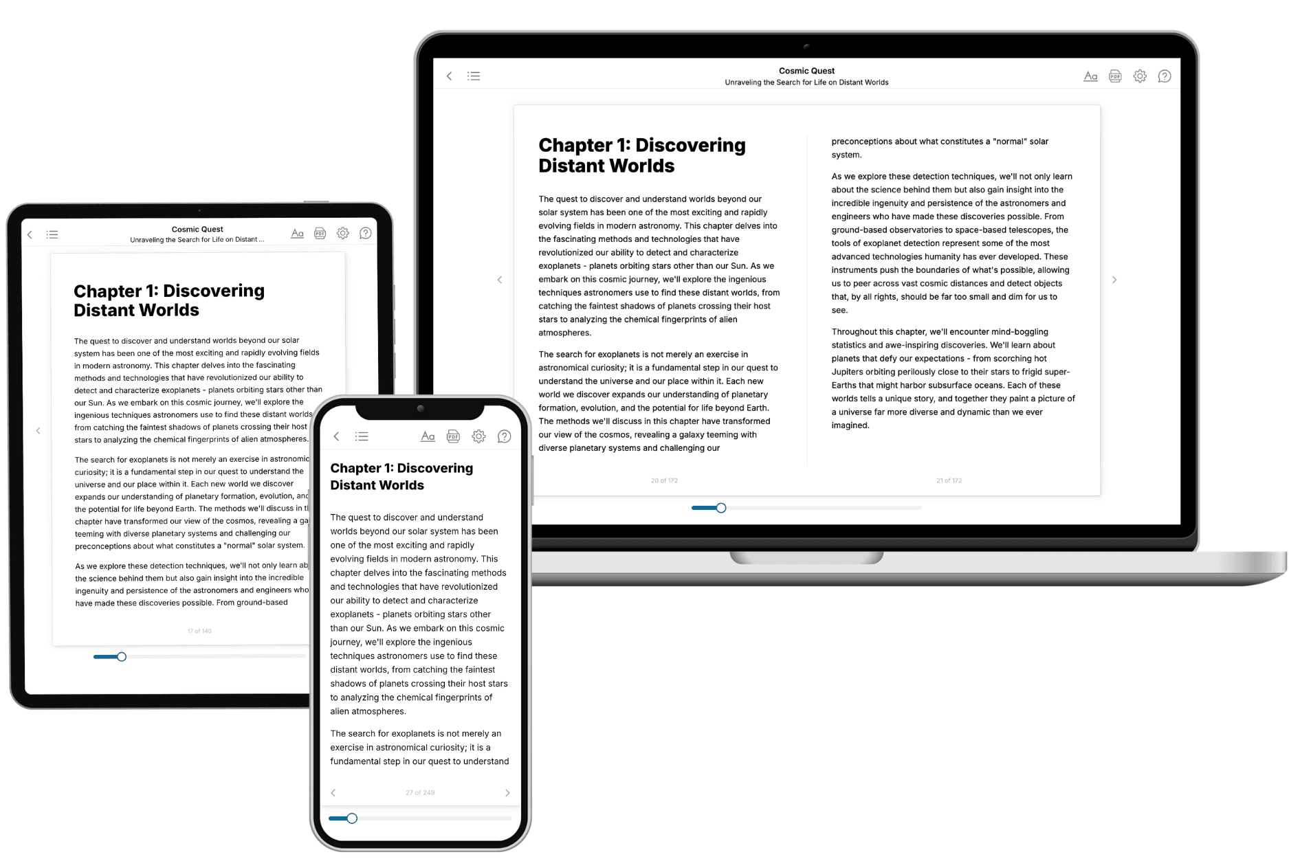
TailoredRead creates complete, full-length nonfiction ebooks, written specifically for you. Tell us what you want to learn and why, and TailoredRead writes you a complete ebook on it, with charts, tables, and diagrams throughout. Read it online, on Kindle, or on any e-reader, or download it as a PDF or EPUB. Every book is written fresh the day you order it.
- How is the book tailored to me?
Before anything is written, you answer a few short questions about your goals, your background, and the topics you care about. Your book is then planned around your answers: written at your level, focused on your goals, and covering the topics you chose, instead of the one-size-fits-all book a store sells everyone.
- Will it read like generic AI content?
No. Your book isn't a chat transcript: it's planned chapter by chapter before a single word is written, told in a clear book voice, and explains ideas visually with charts, tables, and diagrams. After writing, every book goes through an editorial pass that polishes chapters so the book reads consistent from start to finish. Judge for yourself: browse thousands of sample books on our Explore Books page.
- How accurate is the content?
Our AI first checks whether your subject needs live research. Niche and fast-moving subjects are researched before writing, and the book plan and chapters are grounded in what it finds. After writing, every book goes through a quality pass that checks its facts and consistency, and researched books list their sources in a Notes section at the back.
- How long is the book?
You choose the length: Comprehensive (250-300 pages), Detailed (150-200 pages), Essential (70-100 pages), or Short (30-50 pages).
- Does the book include visuals?
Yes. Every book includes charts, tables, and diagrams: timelines, checklists, step-by-step guides, decision trees, comparison tables, matrices, and bar charts. A typical book includes dozens of these visual elements.
- Can I read it on Kindle? What formats can I download?
Yes. Every book can be read in our online reader or downloaded as a PDF or EPUB. The EPUB can be opened with Kindle, Apple Books, Kobo, and any e-reader. The Commercial and Author licenses also include an editable Word (DOCX) and Markdown download.
- How much does it cost?
About the price of a regular ebook. The exact price depends on your book's length and complexity, from $2 for the shortest books to $35 for the most comprehensive, and it's shown when you review your book, before you commit to anything. Each book is a one-time purchase, yours to keep, no subscription. Licenses that let you share, teach, or publish your book range from $35.99 to $49.99.
- Can I preview the book before purchasing?
Before you pay, you'll see what your book will cover: the title, a detailed description, the estimated length, and the complete chapter-by-chapter table of contents, so you know what you're getting before you decide. The full text itself is written after you purchase.
- How long does it take to create a book?
About 10 minutes. You can start reading the opening chapters while the rest is still being written.