Electrical Wiring Diagrams Mastery
From Symbols to Schematics: A Practical Guide to Reading and Creating Technical Drawings
Master the art and science of electrical wiring diagrams and take your technical drawing skills to the next level.
222 pages10 chaptersJan 20, 2026Electrical Engineering
About this book
This comprehensive guide bridges the gap between basic symbol recognition and professional-grade diagram creation, equipping you with the knowledge to interpret complex electrical systems and communicate designs with absolute clarity. You'll discover how standardized symbols, color conventions, and annotation practices work together to create diagrams that prevent costly mistakes and ensure safety. Through practical examples, real-world case studies, and step-by-step instructions, you'll learn to navigate single-line diagrams, multi-line schematics, and control circuits with confidence. Whether you're designing new systems, troubleshooting existing installations, or collaborating with engineering teams, this book provides the essential framework for reading, creating, and validating electrical wiring diagrams that meet industry standards and best practices.
Table of contents
- IntroductionWhy Electrical Wiring Diagrams Matter, How to Use This Book, Industry Standards and Best Practices OverviewRead below
- Chapter 1: Fundamentals of Electrical Wiring DiagramsWhat Is a Wiring Diagram?, Types of Electrical Diagrams, Purpose and Real-World Applications
- Chapter 2: Standardized Symbols and ConventionsCommon Electrical Symbols, How Components Are Represented, NFPA and IEC Symbol Standards, Interpreting Symbol Variations Across Standards
- Chapter 3: Reading Single-Line DiagramsSingle-Line Diagram Basics, Power Distribution Representation, Interpreting Protective Devices and Ratings, Practical Single-Line Examples
- Chapter 4: Understanding Multi-Line and Schematic DiagramsMulti-Line Diagram Structure, Schematic Versus Pictorial Representations, Circuit Tracing and Path Following, Multi-Line Case Studies
- Chapter 5: Color Coding and Line StylesWire Color Standards and Meanings, Line Styles and What They Communicate, Color Coding Best Practices
- Chapter 6: Grounding and Bonding in DiagramsGrounding Symbols and Representations, Bonding Connections and Safety, Equipment Grounding Conductor Representation, Grounding Diagram Examples
- Chapter 7: Labeling, Annotation, and DocumentationEffective Labeling Practices, Annotation Standards and Conventions, Reference Designations and Component Identification, Creating Clear Legends and Notes
- Chapter 8: Creating Accurate Wiring DiagramsPlanning Your Diagram, Manual Drafting Principles, CAD Software Best Practices, Quality Control and Verification Checklist
- Chapter 9: Common Mistakes and How to Avoid ThemSymbol Placement and Orientation Errors, Labeling and Documentation Mistakes, Circuit Logic and Connection Errors, Safety-Critical Oversights
- Chapter 10: Advanced Diagram InterpretationNavigating Multi-Page Diagrams, Control Circuits and Logic Representation, Using Diagrams for Troubleshooting
- ConclusionKey Takeaways, Continuing Your Learning Journey
- Glossary of Terms
- Further Reading and Resources
Introduction
Electrical wiring diagrams serve as the universal language of electrical systems, bridging the gap between conceptual design and physical implementation. Whether you're installing a residential circuit, troubleshooting an industrial control system, or designing a commercial power distribution network, the ability to read and create accurate wiring diagrams is fundamental to your success. These technical drawings communicate complex electrical relationships through standardized symbols, conventions, and visual representations that transcend language barriers and regional differences. For intermediate professionals seeking to advance their careers, mastering this visual language opens doors to more complex projects, leadership roles, and specialized technical positions.
The electrical industry has evolved dramatically over the past few decades, with digital tools and computer-aided design software transforming how diagrams are created and shared. Yet the fundamental principles underlying effective diagram creation remain unchanged: clarity, accuracy, and adherence to established standards. Modern electrical systems have grown increasingly complex, incorporating smart technologies, renewable energy sources, and sophisticated control systems that demand precise documentation. A single misinterpreted symbol or incorrectly labeled connection can result in equipment damage, system failures, or serious safety hazards. The stakes are high, and the margin for error continues to shrink as electrical systems become more integrated and interdependent.
This book builds upon your existing foundational knowledge to develop advanced competencies in reading, interpreting, and creating professional-grade electrical wiring diagrams. You already understand basic electrical principles and have likely encountered various types of diagrams in your work. Now it's time to deepen that understanding, refine your technical drawing skills, and learn the industry standards that separate adequate documentation from exceptional communication. Throughout these chapters, you'll discover practical techniques, real-world applications, and systematic approaches that will transform how you interact with electrical diagrams. The goal is not merely to recognize symbols, but to develop the analytical skills necessary to understand complete electrical systems, anticipate potential issues, and communicate designs with absolute precision.
The journey from reading simple circuit diagrams to creating comprehensive multi-page schematics requires both technical knowledge and practical experience. This book provides the framework for that development, offering structured learning paths that progress from fundamental concepts to advanced applications. You'll explore the differences between single-line diagrams, multi-line schematics, and control circuit representations, understanding when each type is most appropriate. You'll learn how color coding, line styles, and annotation practices work together to create diagrams that are both technically accurate and visually clear. Most importantly, you'll develop the critical thinking skills necessary to validate diagrams, identify errors, and ensure that your technical drawings meet the rigorous standards demanded by modern electrical work.
Why Electrical Wiring Diagrams Matter
Electrical wiring diagrams are far more than simple technical drawings—they are critical safety documents that protect lives, preserve equipment, and ensure system reliability. When an electrician opens a panel to troubleshoot a fault, the wiring diagram becomes their roadmap through a potentially dangerous environment. A clear, accurate diagram allows them to identify circuits, trace power paths, and isolate problems without unnecessary exposure to energized conductors. Conversely, a poorly drawn or outdated diagram can lead technicians into hazardous situations, causing them to make incorrect assumptions about circuit states or connection points. The National Fire Protection Association estimates that electrical failures or malfunctions cause approximately 13% of home structure fires annually, many of which could be prevented through better documentation and understanding of electrical systems[1].
Beyond safety considerations, wiring diagrams serve as essential communication tools that enable collaboration across diverse teams and disciplines. Consider a commercial building project where electrical engineers, general contractors, HVAC technicians, and building automation specialists must coordinate their work. The electrical wiring diagrams provide a common reference point that allows each team to understand how their systems interact with the electrical infrastructure. Without standardized diagrams, each trade might make conflicting assumptions about circuit availability, load capacities, or control interfaces. This coordination function becomes even more critical in renovation projects, where existing systems must be documented before modifications can be safely planned and executed.
The economic impact of accurate wiring diagrams extends throughout a project's lifecycle, from initial design through decades of operation and maintenance. During the design phase, clear diagrams enable accurate material takeoffs and cost estimates, reducing the risk of budget overruns caused by missing components or incorrect specifications. During installation, well-organized diagrams minimize confusion and rework, allowing electricians to complete their tasks efficiently and correctly the first time. A study by the Construction Industry Institute found that poor project documentation, including inadequate electrical drawings, contributes to productivity losses of 10-15% on typical construction projects[2]. Over the operational lifetime of a facility, comprehensive as-built diagrams reduce troubleshooting time, facilitate system upgrades, and preserve institutional knowledge even as personnel change.
Regulatory compliance represents another critical dimension where wiring diagrams prove indispensable. Electrical codes and standards, such as the National Electrical Code (NEC) in the United States or the International Electrotechnical Commission (IEC) standards globally, establish specific requirements for electrical installations. Inspectors rely on submitted diagrams to verify that proposed installations meet code requirements before issuing permits. During inspections, diagrams serve as verification tools to confirm that installed systems match approved plans. For facilities subject to specialized regulations—such as healthcare facilities, hazardous locations, or food processing plants—detailed wiring diagrams become part of the permanent compliance documentation that must be maintained and updated throughout the facility's operational life.
The diagnostic value of wiring diagrams becomes most apparent during troubleshooting and emergency response situations. When equipment fails or circuits malfunction, technicians must quickly identify the problem source and implement solutions with minimal downtime. A comprehensive wiring diagram allows systematic troubleshooting by revealing the relationships between components, showing protective device locations, and indicating normal operating parameters. For example, when a motor fails to start, the diagram helps technicians trace the control circuit, identify interlock conditions, and verify that all safety devices are properly configured. Without accurate diagrams, troubleshooting becomes a time-consuming process of trial and error, potentially causing additional damage or extended outages.
Modern electrical systems increasingly incorporate digital controls, programmable logic controllers, and networked devices that add layers of complexity to traditional power distribution. These advanced systems require diagrams that clearly distinguish between power circuits, control circuits, and communication networks while showing how these elements interact. Consider a building automation system that controls lighting, HVAC, and security systems through a network of sensors and controllers. The wiring diagrams must show not only the power supplies for each device but also the communication pathways, network topology, and integration points with other systems. As electrical systems continue to evolve toward greater automation and intelligence, the importance of clear, comprehensive documentation only increases.
Professional reputation and liability considerations also underscore the importance of quality wiring diagrams. Electrical contractors and engineers who consistently produce clear, accurate documentation build reputations for professionalism and competence that lead to repeat business and referrals. Conversely, those who submit incomplete or error-filled diagrams may face project delays, disputes over change orders, and potential liability for installation errors. In litigation involving electrical failures or accidents, wiring diagrams often become key evidence in determining whether installations met applicable standards and whether proper documentation was provided. The quality of your diagrams reflects directly on your professional credibility and can have lasting impacts on your career trajectory.
Educational and knowledge transfer functions represent a final critical dimension of wiring diagram importance. For apprentices and junior technicians, studying well-crafted diagrams provides insights into proper design practices, standard conventions, and systematic approaches to electrical system organization. Diagrams serve as teaching tools that illustrate concepts more effectively than verbal descriptions alone. When experienced professionals retire or move to new positions, comprehensive diagrams preserve their knowledge and design decisions for future generations. This knowledge preservation function becomes particularly valuable in facilities with long operational lifetimes, where the original designers may be long gone but their documentation continues to guide maintenance and modification decisions for decades.
How to Use This Book
This book is structured to build your skills progressively, moving from foundational concepts through increasingly complex applications. Each chapter focuses on specific aspects of electrical wiring diagrams, providing both theoretical understanding and practical application guidance. The early chapters establish essential knowledge about diagram types, symbols, and conventions that form the foundation for all subsequent learning. Middle chapters explore specific diagram categories and techniques in depth, while later chapters address advanced topics like troubleshooting, quality control, and common pitfalls. This progression allows you to develop competencies systematically, ensuring that each new concept builds upon previously mastered material.
Your approach to this book should align with your current skill level and specific learning objectives. If you're relatively new to technical drawing or seeking comprehensive knowledge, working through chapters sequentially provides the most effective learning path. This approach ensures you don't miss foundational concepts that later chapters assume you understand. However, if you're an experienced professional seeking to address specific knowledge gaps or refresh particular skills, the book's modular structure allows you to focus on relevant chapters. For example, if you're comfortable reading diagrams but need to improve your creation skills, you might focus primarily on Chapters 7 and 8, referring back to earlier chapters as needed for specific symbol or convention questions.
Each chapter includes practical examples, case studies, and real-world scenarios designed to reinforce theoretical concepts through application. These examples are not merely illustrative—they represent actual situations you're likely to encounter in professional practice. As you work through each chapter, take time to study these examples carefully, considering not just what the diagram shows but why it's organized in a particular way. Try to anticipate what information the diagram creator was trying to communicate and how effectively they achieved that goal. This analytical approach develops the critical thinking skills necessary to evaluate and improve your own diagram work. Consider keeping a notebook where you sketch your own versions of example diagrams or create variations that apply the concepts to systems you work with regularly.
The book emphasizes both traditional manual drafting principles and modern CAD software practices, recognizing that professional competence requires understanding both approaches. While most contemporary diagram creation occurs in digital environments, the fundamental principles of clear communication, logical organization, and standard conventions remain constant regardless of tools. Understanding manual drafting principles actually enhances your effectiveness with CAD software by helping you recognize when automated features might compromise clarity or when manual adjustments are necessary. As you progress through the chapters, practice applying concepts using whatever tools you have available—whether that's pencil and paper, general-purpose drawing software, or specialized electrical CAD applications.
Active engagement with the material significantly enhances learning outcomes compared to passive reading. Throughout the book, you'll encounter opportunities to apply concepts to your own work situations. Take advantage of these opportunities by gathering examples of diagrams from your workplace or professional projects. Analyze these real-world diagrams using the frameworks and criteria presented in each chapter. Identify strengths and weaknesses, consider how the diagrams might be improved, and think about how the principles discussed apply to your specific industry or application area. This connection between book content and your professional context transforms abstract concepts into practical skills you can immediately apply.
The book includes numerous references to industry standards, codes, and best practices that govern electrical diagram creation. While you don't need to memorize every standard, familiarizing yourself with the major frameworks—particularly those relevant to your geographic region and industry sector—is essential for professional practice. Consider obtaining copies of key standards documents referenced throughout the book, such as:
- National Electrical Code (NEC/NFPA 70) for North American electrical installations
- IEC 60617 for international graphical symbols used in electrical diagrams
- IEEE Standard 315 for graphic symbols for electrical and electronics diagrams
- ANSI Y32.2 for graphic symbols for electrical wiring and layout diagrams
Quality control and self-assessment are critical components of skill development in technical drawing. As you complete each chapter, review the key concepts and assess your understanding honestly. Can you explain the concepts to a colleague? Can you apply the techniques to create or interpret diagrams in your work? The book provides checklists and verification frameworks in several chapters—use these tools to evaluate your own diagram work and identify areas needing improvement. Consider establishing a peer review arrangement with colleagues where you exchange diagrams for constructive feedback. This collaborative approach accelerates learning and helps identify blind spots or habits that might compromise diagram quality.
The book's structure supports both initial learning and ongoing reference use throughout your career. After completing your first read-through, keep the book accessible in your work environment for quick reference when questions arise. The detailed table of contents and organized chapter structure make it easy to locate specific information when you need to verify a symbol meaning, check a convention, or review best practices for a particular diagram type. Many professionals find it helpful to mark particularly relevant sections with tabs or annotations, creating a personalized quick-reference guide tailored to their specific work context. Over time, as you encounter new diagram challenges or expand into different electrical system types, returning to relevant chapters provides refreshers and deeper insights that weren't apparent during initial reading.
Finally, recognize that mastering electrical wiring diagrams is an ongoing journey rather than a destination. The electrical industry continues to evolve, with new technologies, updated standards, and emerging best practices constantly reshaping how diagrams are created and used. Use this book as a foundation for continuous professional development, supplementing it with industry publications, professional organization resources, and ongoing training opportunities. The "Further Reading and Resources" section at the book's end provides starting points for extended learning. By maintaining a commitment to continuous improvement and staying current with industry developments, you'll ensure that your diagram skills remain sharp and relevant throughout your career.
Industry Standards and Best Practices Overview
Industry standards for electrical wiring diagrams exist to ensure consistency, safety, and effective communication across projects, organizations, and geographic regions. These standards establish common symbol sets, drawing conventions, and documentation practices that allow any qualified professional to interpret diagrams accurately, regardless of who created them. The primary standards organizations governing electrical diagram practices include the National Fire Protection Association (NFPA), the Institute of Electrical and Electronics Engineers (IEEE), the American National Standards Institute (ANSI), and the International Electrotechnical Commission (IEC). Each organization addresses different aspects of electrical documentation, and professional practice often requires familiarity with multiple standards depending on project scope, location, and industry sector.
The National Electrical Code (NEC), published by NFPA as NFPA 70, serves as the foundational safety standard for electrical installations in the United States. While the NEC primarily addresses installation requirements rather than diagram conventions, it establishes terminology, component specifications, and safety practices that directly influence how diagrams must be drawn. For example, NEC requirements for grounding and bonding systems dictate how these critical safety elements must be represented in diagrams. The NEC operates on a three-year revision cycle, with the 2023 edition representing the current version at the time of this writing. Staying current with NEC updates is essential because code changes often introduce new requirements that affect diagram content and organization. Many jurisdictions adopt the NEC with local amendments, so understanding both the base code and local modifications is necessary for compliance.
IEEE Standard 315, "Graphic Symbols for Electrical and Electronics Diagrams," provides comprehensive symbol definitions used throughout North American electrical practice. This standard establishes the visual representations for components ranging from basic resistors and capacitors to complex motor controls and instrumentation devices. IEEE 315 emphasizes clarity and unambiguous representation, specifying not only symbol shapes but also orientation conventions and modification methods for indicating component variations. For instance, the standard defines how to show normally open versus normally closed contacts, how to indicate adjustable components, and how to represent multi-pole devices. Familiarity with IEEE 315 ensures that your diagrams use symbols that other professionals will immediately recognize and correctly interpret.
The IEC 60617 series represents the international standard for graphical symbols in electrical diagrams, used primarily in Europe, Asia, and other regions following IEC conventions. While IEEE and IEC symbols share many similarities, significant differences exist that can cause confusion when working across international boundaries. For example, IEC and IEEE use different symbols for certain protective devices, control components, and measurement instruments. A circuit breaker might be represented differently in an IEC-compliant diagram compared to an IEEE-compliant version, even though both symbols are technically correct within their respective standards. When working on international projects or with multinational organizations, understanding both symbol systems and clearly indicating which standard your diagrams follow becomes essential for avoiding misinterpretation.
ANSI Y32.2 and related standards address specific aspects of electrical wiring and layout diagrams, providing detailed guidance on drawing conventions, line styles, and annotation practices. These standards specify technical details such as:
- Line weights and styles for different conductor types and system voltages
- Spacing and organization conventions for multi-line diagrams
- Reference designation systems for component identification
- Title block requirements and drawing sheet organization
- Revision tracking and version control practices
Beyond formal standards, industry best practices have evolved through decades of professional experience and represent collective wisdom about what works effectively in real-world applications. These practices often address situations not explicitly covered by standards or provide guidance on choosing between multiple acceptable approaches. For example, standards might permit several different methods for representing a particular circuit configuration, but best practices suggest which method provides the clearest communication for specific applications. Industry associations, professional organizations, and experienced practitioners share these best practices through publications, training programs, and mentorship relationships. Engaging with professional communities—such as local IAEI chapters, IEEE sections, or trade-specific organizations—provides access to this practical knowledge that complements formal standards.
Quality management systems and project-specific standards often layer additional requirements onto base industry standards. Large organizations, government agencies, and major industrial facilities frequently maintain internal standards that specify exactly how diagrams must be formatted, what information must be included, and what review processes must be followed. These internal standards ensure consistency across projects and facilitate long-term maintenance by establishing uniform documentation practices. When working with such organizations, understanding their specific requirements is just as important as knowing general industry standards. Request style guides, template files, and example diagrams early in any project to ensure your work meets client-specific expectations from the start.
The relationship between standards compliance and legal liability deserves careful consideration. While following industry standards doesn't guarantee legal protection in all circumstances, significant deviations from accepted practices can create liability exposure if installations fail or accidents occur. Courts often consider whether professionals followed applicable standards when evaluating negligence claims. Documentation that clearly demonstrates standards compliance—through proper symbol usage, adequate labeling, and appropriate safety notations—provides evidence of professional diligence. Conversely, diagrams that ignore established conventions or omit critical safety information may be viewed as evidence of negligence. This legal dimension reinforces the practical importance of understanding and consistently applying industry standards in all diagram work.
Standards evolution and updates present ongoing challenges for practicing professionals. As electrical technology advances—incorporating renewable energy systems, energy storage, electric vehicle charging, and smart grid technologies—standards organizations work to develop appropriate symbols and conventions for these new applications. The lag between technology deployment and standards publication means you'll sometimes encounter situations where no established symbol exists for a particular component or configuration. In these cases, creating clear, logical representations based on analogous existing symbols, providing detailed legends explaining your notation, and documenting your rationale becomes necessary. Many innovations in diagram conventions begin as individual solutions to novel problems before eventually being incorporated into formal standards through the consensus development process.
Practical application of standards requires balancing strict compliance with effective communication. Standards provide frameworks and guidelines, but they cannot address every possible situation or application. Professional judgment remains essential for determining how to apply standards to specific circumstances, when deviations might be justified for clarity, and how to handle situations where different standards conflict. For example, space constraints on a drawing might make strict adherence to spacing conventions impractical, requiring thoughtful compromises that maintain clarity while accommodating physical limitations. Developing this judgment comes through experience, mentorship, and careful study of how experienced professionals navigate the tension between standards compliance and practical effectiveness. The goal is not rigid adherence to rules for their own sake, but rather using standards as tools to achieve the ultimate objective: clear, accurate communication of electrical system information that enables safe, effective installation and maintenance.
This is the end of the free sample. The full book has 10 chapters.
Want this book written for you?
Tell us your goals and background, and get your own version of this book, tailored by AI to you.


Benefits of AI-tailored books
- Read one book, not ten:
- all the Electrical Engineering knowledge you need, gathered into a single book.
- Save days of learning:
- tell us your goals, choose your topics, and the whole book is built around them.
- Learn effortlessly:
- Electrical Engineering book written for your specific background and expertise.
- Understand at a glance:
- includes charts, tables, timelines, checklists, decision trees, and more.
- Stay current:
- written the day you order it, not years ago.
- Trust what you read:
- every book is checked for accuracy, with real research when your subject needs it.
Create your unique book in 3 steps
- 1. Select your focus
Select the focus of your Electrical Engineering book and share your background
- 2. Personalize your book
Specify your goals and choose sub-topics to include
- 3. Get your tailored book
Your book is ready in 10 minutes. Read it online, download as EPUB or PDF, or send to Kindle.


Frequently asked questions
- What is TailoredRead?
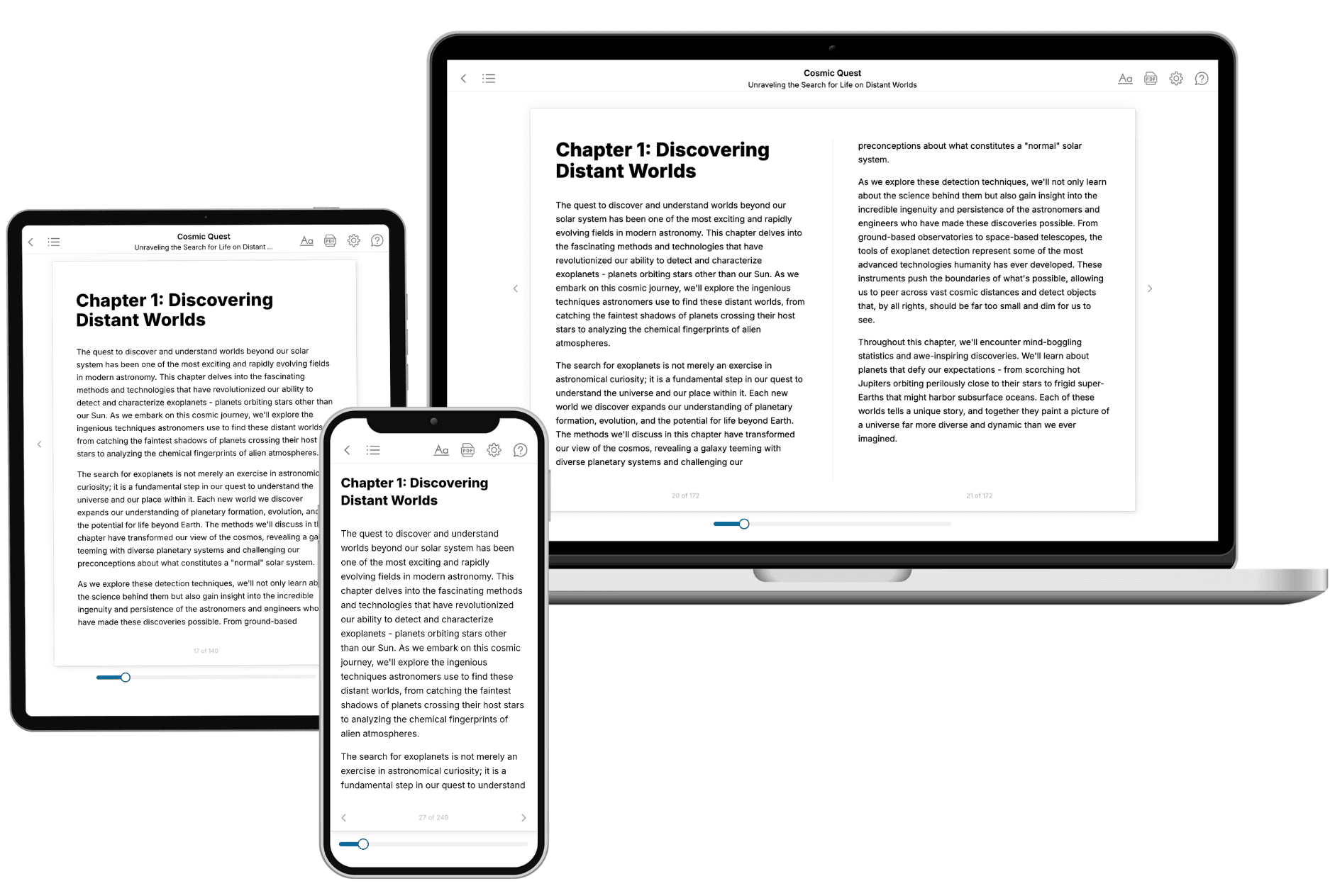
TailoredRead creates complete, full-length nonfiction ebooks, written specifically for you. Tell us what you want to learn and why, and TailoredRead writes you a complete ebook on it, with charts, tables, and diagrams throughout. Read it online, on Kindle, or on any e-reader, or download it as a PDF or EPUB. Every book is written fresh the day you order it.
- How is the book tailored to me?
Before anything is written, you answer a few short questions about your goals, your background, and the topics you care about. Your book is then planned around your answers: written at your level, focused on your goals, and covering the topics you chose, instead of the one-size-fits-all book a store sells everyone.
- Will it read like generic AI content?
No. Your book isn't a chat transcript: it's planned chapter by chapter before a single word is written, told in a clear book voice, and explains ideas visually with charts, tables, and diagrams. After writing, every book goes through an editorial pass that polishes chapters so the book reads consistent from start to finish. Judge for yourself: browse thousands of sample books on our Explore Books page.
- How accurate is the content?
Our AI first checks whether your subject needs live research. Niche and fast-moving subjects are researched before writing, and the book plan and chapters are grounded in what it finds. After writing, every book goes through a quality pass that checks its facts and consistency, and researched books list their sources in a Notes section at the back.
- How long is the book?
You choose the length: Comprehensive (250-300 pages), Detailed (150-200 pages), Essential (70-100 pages), or Short (30-50 pages).
- Does the book include visuals?
Yes. Every book includes charts, tables, and diagrams: timelines, checklists, step-by-step guides, decision trees, comparison tables, matrices, and bar charts. A typical book includes dozens of these visual elements.
- Can I read it on Kindle? What formats can I download?
Yes. Every book can be read in our online reader or downloaded as a PDF or EPUB. The EPUB can be opened with Kindle, Apple Books, Kobo, and any e-reader. The Commercial and Author licenses also include an editable Word (DOCX) and Markdown download.
- How much does it cost?
About the price of a regular ebook. The exact price depends on your book's length and complexity, from $2 for the shortest books to $35 for the most comprehensive, and it's shown when you review your book, before you commit to anything. Each book is a one-time purchase, yours to keep, no subscription. Licenses that let you share, teach, or publish your book range from $35.99 to $49.99.
- Can I preview the book before purchasing?
Before you pay, you'll see what your book will cover: the title, a detailed description, the estimated length, and the complete chapter-by-chapter table of contents, so you know what you're getting before you decide. The full text itself is written after you purchase.
- How long does it take to create a book?
About 10 minutes. You can start reading the opening chapters while the rest is still being written.