Geometric Dimensioning and Tolerancing Essentials
Master GD&T for Precision Engineering and Technical Drawing
Navigate the complexities of precision engineering with a clear, practical approach to Geometric Dimensioning and Tolerancing.
253 pages12 chaptersMar 8, 2026Technical Drawing
About this book
This guide takes you from foundational concepts through advanced applications, showing you how to read, interpret, and create GD&T callouts that communicate exactly what your designs require. You'll discover why GD&T matters beyond the drawing—how it impacts manufacturing feasibility, inspection procedures, and ultimately, product quality and cost. Through real-world examples and step-by-step explanations, you'll learn to select the right geometric characteristics for your design intent, establish proper datum references, and apply material conditions correctly. Whether you're refining existing drawings or creating new designs from scratch, this book equips you with the knowledge to ensure your technical drawings are precise, manufacturable, and inspectable. Master the language of modern engineering and eliminate ambiguity in your designs.
Table of contents
- IntroductionWhy GD&T Matters in Modern Engineering, Limitations of Traditional Dimensioning, How to Use This Book, GD&T Standards and FrameworksRead below
- Chapter 1: Fundamentals of Geometric Dimensioning and TolerancingWhat is GD&T and Why It Exists, Communicating Design Intent Precisely, GD&T Versus Traditional Plus-Minus Tolerancing, Key Benefits: Cost, Quality, and Clarity
- Chapter 2: Understanding Datums and Reference FramesWhat Are Datums and Why They're Essential, Selecting Datums Based on Functional Requirements, Primary, Secondary, and Tertiary Datums, Building the Datum Reference Frame
- Chapter 3: Form Characteristics: Controlling ShapeIntroduction to Form Characteristics, Straightness: Controlling Linear Elements, Flatness: Controlling Planar Surfaces, Circularity and Cylindricity: Controlling Roundness
- Chapter 4: Orientation Characteristics: Controlling Angles and AlignmentIntroduction to Orientation Characteristics, Angularity: Controlling Angular Relationships, Perpendicularity: Controlling 90-Degree Relationships, Parallelism: Controlling Parallel Surfaces and Features
- Chapter 5: Location Characteristics: Controlling Position and SymmetryIntroduction to Location Characteristics, Position: The Most Powerful GD&T Tool, Concentricity: Controlling Center Alignment, Symmetry: Controlling Balanced Features
- Chapter 6: Runout Characteristics: Controlling Rotation and WobbleIntroduction to Runout Characteristics, Circular Runout: Controlling Rotation at a Single Plane, Total Runout: Controlling Rotation Along an Axis, Practical Applications of Runout Controls
- Chapter 7: Material Conditions and ModifiersUnderstanding Material Condition Modifiers, Maximum Material Condition (MMC): Expanding Tolerance Zones, Least Material Condition (LMC): Strategic Applications, Regardless of Feature Size (RFS): When to Use It
- Chapter 8: Tolerance Zones and Geometric InterpretationWhat Are Tolerance Zones and How They Work, Visualizing Tolerance Zones in 3D Space, How Zone Geometry Affects Manufacturing and Inspection, Bonus Tolerance: Maximizing Manufacturing Flexibility
- Chapter 9: Applying GD&T to Common Features and AssembliesControlling Holes and Fastener Patterns, Controlling Mating Surfaces and Interfaces, Controlling Rotating Components and Shafts, GD&T Considerations for Assemblies and Stack-ups
- Chapter 10: Reading and Interpreting GD&T DrawingsDecoding GD&T Symbols and Callout Boxes, Understanding Feature Control Frames, Interpreting Complex GD&T Callouts, Common Misinterpretations and How to Avoid Them
- Chapter 11: Creating Effective GD&T SpecificationsIntegrating GD&T into Your Design Process, Selecting the Right Characteristics for Your Design, Determining Appropriate Tolerance Values, Best Practices for Clear and Unambiguous Documentation
- Chapter 12: GD&T and Manufacturing: From Design to ProductionEnsuring Your GD&T Specifications Are Manufacturable, Understanding Process Capability and GD&T Alignment, Connecting GD&T to Inspection and Measurement Methods, Using GD&T to Optimize Cost Without Sacrificing Quality
- ConclusionYour Path to GD&T Mastery, Continuing Your GD&T Journey
- Glossary of GD&T Terms
- Further Reading and Resources
Introduction
Every engineered product starts as an idea, then becomes a drawing, and finally takes physical form in a factory somewhere. That journey from concept to component depends entirely on how well the drawing communicates what the designer intended. When that communication breaks down, parts don't fit, assemblies fail, and production lines grind to a halt. Geometric Dimensioning and Tolerancing, known universally as GD&T, exists to close that gap. It is a standardized symbolic language that tells manufacturers and inspectors not just what a part should look like, but exactly how much variation is acceptable and where it matters most.
If you've spent any time working with engineering drawings, you've almost certainly encountered GD&T symbols. Maybe you've seen a circle with a cross inside it next to a tolerance value, or a small rectangular box containing a series of symbols and numbers attached to a feature. These callouts carry precise, unambiguous meaning. They define tolerance zones in three-dimensional space, establish reference frameworks for measurement, and specify how features must relate to one another. Learning to read and write this language fluently is one of the most valuable skills an engineer or technician can develop.
This book is built for professionals who already understand the basics of engineering drawing and want to move beyond guesswork and approximation. Whether you're an engineer creating new designs, a technician interpreting drawings on the shop floor, or a quality professional setting up inspection procedures, the chapters ahead will give you a structured, practical foundation in GD&T. The goal isn't just to memorize symbols. It's to understand the reasoning behind each tool so you can apply them with confidence and judgment in real-world situations.
The chapters are organized to build your knowledge progressively. You'll start with the foundational concepts, move through each category of geometric characteristic, explore material condition modifiers and tolerance zones, and finish with practical guidance on creating and interpreting complete GD&T specifications. Along the way, you'll find concrete examples, common pitfalls to avoid, and clear explanations of how each concept connects to manufacturing and inspection reality. By the end, GD&T won't feel like a foreign language. It will feel like a tool you reach for naturally whenever precision matters.
Why GD&T Matters in Modern Engineering
Modern manufacturing is a global, distributed activity. A design created in one country might be manufactured in another and assembled in a third. Components from dozens of suppliers must fit together reliably, often with tolerances measured in thousandths of an inch or hundredths of a millimeter. In this environment, ambiguity in a drawing isn't just inconvenient. It's expensive. GD&T provides the standardized framework that makes precise communication possible across languages, time zones, and manufacturing cultures.
Consider a simple example: a bolt hole pattern on a mounting flange. Using traditional plus-minus dimensioning, you might specify the hole locations with X and Y coordinates and a tolerance of ±0.010 inches on each. That sounds precise, but it creates a square tolerance zone. A hole that sits exactly 0.010 inches off in both X and Y simultaneously is actually 0.014 inches away from its true position, yet it passes inspection. GD&T's position control replaces that square zone with a circular one, which more accurately reflects the functional requirement and, as a bonus, allows more parts to pass inspection without sacrificing assembly performance.[1]
GD&T also matters because it connects design intent directly to inspection. When a designer specifies a flatness tolerance on a sealing surface, they're communicating that the surface must lie within two parallel planes a specific distance apart. An inspector with a coordinate measuring machine (CMM) can verify that requirement precisely. There's no interpretation required, no back-and-forth between engineering and quality, and no ambiguity about whether a part passes or fails. That clarity saves time and reduces the risk of accepting bad parts or rejecting good ones.
The financial impact of GD&T is significant and well-documented. Studies in manufacturing engineering consistently show that poorly specified tolerances are a leading cause of rework, scrap, and supplier disputes.[2] When tolerances are too tight, manufacturing costs rise unnecessarily. When they're too loose or ambiguous, parts fail in the field. GD&T gives designers the tools to be precise where precision matters and flexible where it doesn't, striking the right balance between quality and cost.
Beyond individual parts, GD&T becomes even more critical at the assembly level. Tolerance stack-up analysis, which predicts how individual part variations accumulate in an assembly, depends on clearly defined geometric controls. Without GD&T, stack-up calculations are rough estimates at best. With it, engineers can model assembly variation mathematically and make informed decisions about where to tighten or loosen tolerances before a single part is manufactured. This kind of front-loaded engineering prevents costly surprises during production launch.
Finally, GD&T matters because it reflects how parts actually function. A shaft running in a bearing doesn't care about its X and Y coordinates in isolation. It cares about its relationship to the bearing bore, its roundness, and its surface finish. GD&T provides the vocabulary to specify those functional relationships directly, rather than forcing designers to approximate them with indirect coordinate measurements. That functional alignment between the drawing and the real world is what makes GD&T not just a drafting convention, but a genuine engineering tool.
Limitations of Traditional Dimensioning
Traditional plus-minus dimensioning has been the backbone of engineering drawing for well over a century. It's intuitive, easy to apply, and familiar to almost everyone who has ever read a technical drawing. You specify a nominal dimension and add a tolerance band above and below it. Simple. But that simplicity comes with serious limitations that become more apparent as parts get more complex and tolerances get tighter.
The most fundamental problem with plus-minus tolerancing is that it creates rectangular tolerance zones. When you specify a hole location as X = 2.000 ± 0.010 and Y = 1.500 ± 0.010, you're defining a square region where the hole center can legally fall. But the functional requirement for most hole patterns is radial, not rectangular. A bolt must pass through the hole regardless of which direction it's offset. The square zone allows more variation in the diagonal direction than the functional requirement actually permits, and it's inconsistent in how it treats different directions of deviation.
Another major limitation is that plus-minus tolerancing doesn't distinguish between size and form. If you specify a shaft diameter as 1.000 ± 0.005 inches, that tolerance controls the size of the shaft, but it says nothing about whether the shaft is straight, round, or cylindrical. A shaft could be within the size tolerance at every cross-section but still be bowed along its length. In many applications, that bow would cause the shaft to bind in its bearing or create vibration during rotation. Traditional dimensioning simply doesn't have the vocabulary to address that concern directly.
Plus-minus tolerancing also struggles with angular relationships. Specifying an angle as 45° ± 0.5° seems clear, but the actual linear deviation that results from that angular tolerance depends on how far from the vertex you measure. At 1 inch from the vertex, a 0.5° angular error produces about 0.009 inches of linear deviation. At 10 inches from the vertex, the same angular error produces 0.087 inches of deviation. The tolerance means something very different depending on the feature's size, and traditional dimensioning provides no way to account for that relationship.
Consider a real-world scenario that illustrates these limitations clearly. A machined bracket has four mounting holes that must align with a mating plate. The designer specifies the hole locations with plus-minus coordinate tolerances. During inspection, all four holes pass their individual coordinate checks. But when the bracket is assembled to the plate, the bolts won't go in because the holes are offset in a consistent diagonal direction that the square tolerance zones allowed but the circular bolt pattern couldn't accommodate. The drawing was technically correct, but the part didn't work. GD&T's position control with a circular tolerance zone would have caught this problem before any parts were made.
There's also the problem of ambiguity in how plus-minus tolerances are interpreted. When a drawing says a surface must be flat within ±0.005 inches, does that mean each point on the surface must be within 0.005 inches of the nominal plane? Or does it mean the total variation across the surface must be within 0.010 inches? Different inspectors and different companies interpret this differently, leading to disputes and inconsistent quality. GD&T's flatness control eliminates this ambiguity by defining a specific tolerance zone: two parallel planes separated by the tolerance value, within which the entire surface must lie.
The limitations of traditional dimensioning aren't a reason to abandon it entirely. For simple parts with straightforward requirements, plus-minus tolerancing is often perfectly adequate and much faster to apply. The key is knowing when its limitations become a problem. As parts become more complex, as assemblies become tighter, and as manufacturing becomes more distributed, the gaps in traditional dimensioning become harder to ignore. GD&T fills those gaps with precision and clarity that plus-minus tolerancing simply cannot provide.
How to Use This Book
This book is designed to be read sequentially, but it's also structured so you can jump to specific topics when you need a reference. If you're new to GD&T or want to build a solid foundation before diving into specific characteristics, start from Chapter 1 and work through the chapters in order. Each chapter builds on concepts introduced earlier, so the progressive approach will give you the strongest understanding. If you already have some GD&T experience and want to deepen your knowledge in a specific area, the chapter structure makes it easy to navigate directly to what you need.
The book is organized into four broad areas. The first covers foundational concepts, including what GD&T is, how it differs from traditional dimensioning, and how datums work. The second covers the four categories of geometric characteristics: form, orientation, location, and runout. The third covers the more advanced topics of material condition modifiers, tolerance zones, and bonus tolerance. The fourth covers practical application, including how to read complex drawings, create effective specifications, and connect GD&T to manufacturing and inspection reality.
Throughout the book, you'll find several recurring elements designed to reinforce learning and make concepts practical:
- Concrete examples: Every major concept is illustrated with a specific, real-world scenario. These aren't abstract exercises. They're situations you're likely to encounter in actual engineering work.
- Common mistakes: Each chapter highlights the errors that engineers and technicians most frequently make with that topic, along with clear guidance on how to avoid them.
- Practical steps: Where applicable, concepts are broken down into step-by-step processes you can follow when applying GD&T to your own drawings.
- Cross-references: When a concept in one chapter connects to something covered elsewhere, the text points you to the relevant section so you can build connections across topics.
One important note about standards: this book primarily references ASME Y14.5-2018, the current American standard for GD&T, with notes on significant differences from the ISO 1101 standard where relevant. If you're working in an industry or region that uses ISO standards, the core concepts are the same, but some symbols, terminology, and rules differ. Chapter 1's standards overview section covers the key differences so you can navigate both frameworks confidently.
The best way to learn GD&T is to practice applying it. As you read each chapter, try to connect the concepts to drawings you work with regularly. Look at existing drawings and identify the GD&T callouts. Ask yourself why each control was chosen and what would happen if it were removed or changed. When you encounter a design problem in your own work, think about which GD&T tools might address it. This active engagement with the material will accelerate your learning far more than passive reading alone.
Don't be discouraged if some concepts take time to click. GD&T has a reputation for being difficult, and that reputation isn't entirely undeserved. Some of the more advanced topics, like composite position tolerances or simultaneous requirements, require careful thought even for experienced practitioners. The goal of this book is to make those concepts as clear and accessible as possible, but mastery comes with practice and exposure over time. Every drawing you read and every specification you create will deepen your understanding.
Finally, keep this book accessible as a reference. The glossary at the back provides quick definitions for all key terms. The chapter on reading and interpreting GD&T drawings (Chapter 10) is particularly useful as a reference when you encounter an unfamiliar callout on a drawing. Over time, you'll find that you reach for this book less as a learning tool and more as a confirmation resource, which is exactly the sign that the knowledge has become your own.
GD&T Standards and Frameworks
GD&T doesn't exist in a vacuum. It's governed by formal standards that define every symbol, rule, and interpretation. Understanding which standard applies to a given drawing is the first step in reading it correctly. The two dominant frameworks are ASME Y14.5, published by the American Society of Mechanical Engineers, and ISO 1101, published by the International Organization for Standardization. Both accomplish the same fundamental goal, but they differ in important ways that can cause real problems if you mix them up.
ASME Y14.5 is the standard used predominantly in the United States and in many industries with strong American roots, including aerospace, defense, and automotive. The current version is ASME Y14.5-2018, which replaced the widely used 2009 edition. The 2018 revision introduced several clarifications and new concepts, including dynamic profile tolerancing and expanded rules for datum reference frames. Many companies are still working from 2009 drawings, so it's worth knowing both versions. The differences are mostly refinements rather than fundamental changes, but they matter in specific situations.[3]
ISO 1101 is the international standard used widely in Europe, Asia, and in multinational companies that need a single global framework. The ISO GPS (Geometrical Product Specifications) system is broader than ASME Y14.5, encompassing a family of related standards that cover everything from surface texture to coordinate measurement. ISO 1101 itself covers geometric tolerancing specifically. While the core concepts align closely with ASME Y14.5, there are meaningful differences in symbols, default rules, and how certain modifiers are applied.
Here are the most important practical differences between the two standards:
- Default material condition: Under ASME Y14.5, the default condition for geometric tolerances applied to features of size is RFS (Regardless of Feature Size). Under older ISO practice, MMC was sometimes the default, though modern ISO standards have moved closer to the ASME approach.
- Projected tolerance zone: Both standards support projected tolerance zones for fastener applications, but the symbol and application rules differ slightly.
- Envelope principle: ISO applies the envelope principle (Rule #1 equivalent) only when explicitly invoked with the
Esymbol, while ASME Y14.5 applies it by default to individual features of size. - Concentricity and symmetry: ASME Y14.5-2018 has deprecated concentricity and symmetry as standalone controls, recommending position or profile instead. ISO 1101 still includes them as active controls.
For most of this book, the focus is on ASME Y14.5-2018, since it's the most widely used standard in the industries where GD&T is most critical. Where ISO differences are significant enough to affect how you'd interpret or apply a control, those differences are noted explicitly. If you work primarily with ISO drawings, the conceptual foundation you build here will transfer directly. You'll just need to verify the specific symbol conventions and default rules against ISO 1101 for your particular application.
Beyond the primary standards, several supporting documents are worth knowing about. ASME Y14.5.1 provides the mathematical definitions underlying the geometric characteristics, which is essential for CMM programming and software-based inspection. ASME Y14.41 covers digital product definition, which governs how GD&T is applied in 3D model-based definition (MBD) environments where the drawing is replaced by an annotated CAD model. As manufacturing moves increasingly toward MBD workflows, understanding Y14.41 is becoming more important for design engineers.
Industry-specific standards also layer on top of the base GD&T standards. Aerospace companies often follow AS9100 quality management requirements, which influence how GD&T is documented and verified. Automotive suppliers working with major OEMs frequently encounter AIAG standards that specify additional requirements for drawing documentation and measurement system analysis. Defense contractors may work under MIL-STD drawing standards that reference ASME Y14.5 but add specific requirements for certain feature types. Knowing which standards apply to your industry and customer base is part of applying GD&T effectively in practice.
One practical recommendation: always check the drawing's title block or general notes for a standards reference before interpreting any GD&T callout. A drawing that references ASME Y14.5-2009 should be interpreted under 2009 rules, not 2018 rules, even if you're more familiar with the newer version. Similarly, a drawing that references ISO 1101 should be read with ISO conventions in mind. This sounds obvious, but it's a step that gets skipped surprisingly often, leading to misinterpretations that cause real manufacturing problems. The standard reference on the drawing is the authoritative source, and everything else follows from it.
Notes
Introduction
This is the end of the free sample. The full book has 12 chapters.
Want this book written for you?
Tell us your goals and background, and get your own version of this book, tailored by AI to you.


Benefits of AI-tailored books
- Read one book, not ten:
- all the Technical Drawing knowledge you need, gathered into a single book.
- Save days of learning:
- tell us your goals, choose your topics, and the whole book is built around them.
- Learn effortlessly:
- Technical Drawing book written for your specific background and expertise.
- Understand at a glance:
- includes charts, tables, timelines, checklists, decision trees, and more.
- Stay current:
- written the day you order it, not years ago.
- Trust what you read:
- every book is checked for accuracy, with real research when your subject needs it.
Create your unique book in 3 steps
- 1. Select your focus
Select the focus of your Technical Drawing book and share your background
- 2. Personalize your book
Specify your goals and choose sub-topics to include
- 3. Get your tailored book
Your book is ready in 10 minutes. Read it online, download as EPUB or PDF, or send to Kindle.


Frequently asked questions
- What is TailoredRead?
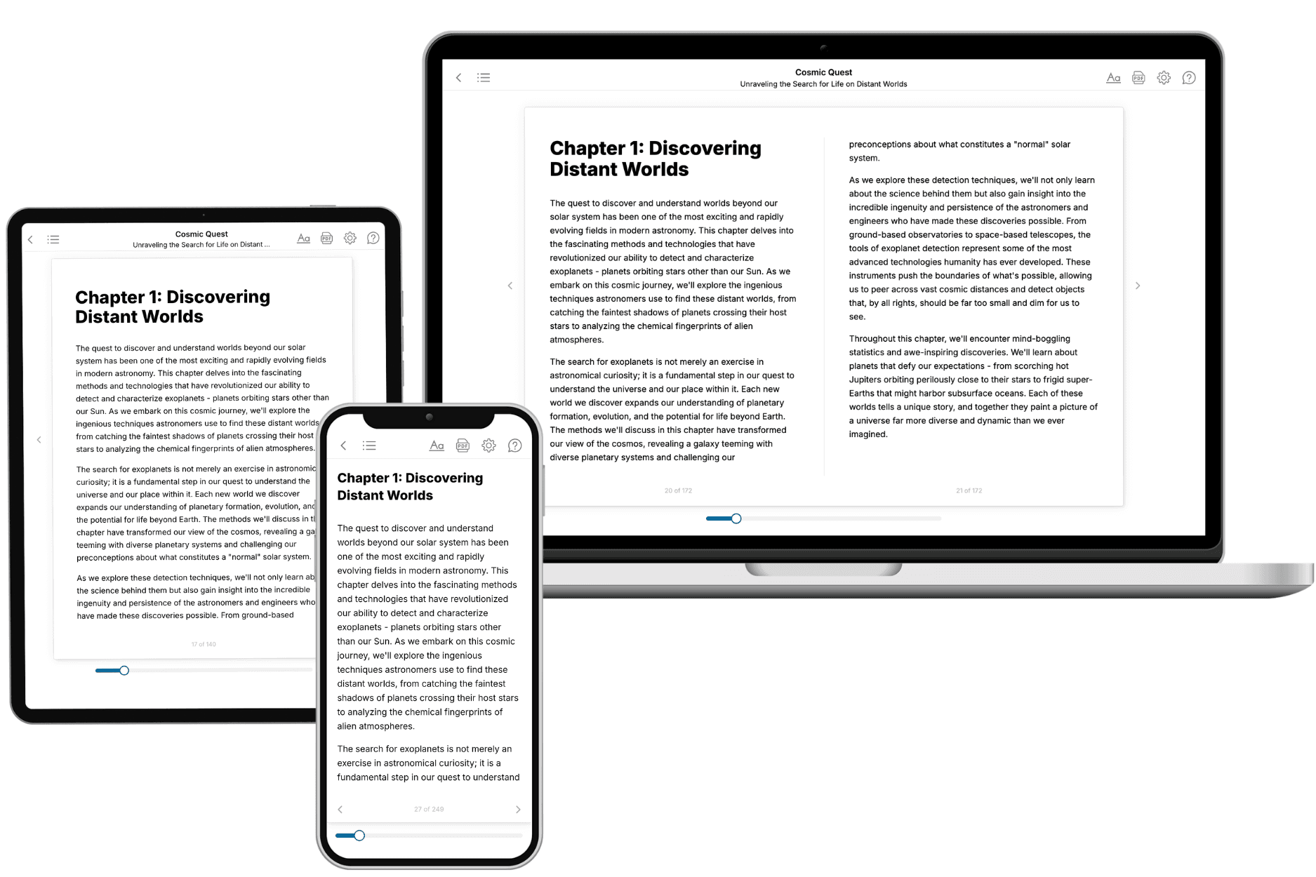
TailoredRead creates complete, full-length nonfiction ebooks, written specifically for you. Tell us what you want to learn and why, and TailoredRead writes you a complete ebook on it, with charts, tables, and diagrams throughout. Read it online, on Kindle, or on any e-reader, or download it as a PDF or EPUB. Every book is written fresh the day you order it.
- How is the book tailored to me?
Before anything is written, you answer a few short questions about your goals, your background, and the topics you care about. Your book is then planned around your answers: written at your level, focused on your goals, and covering the topics you chose, instead of the one-size-fits-all book a store sells everyone.
- Will it read like generic AI content?
No. Your book isn't a chat transcript: it's planned chapter by chapter before a single word is written, told in a clear book voice, and explains ideas visually with charts, tables, and diagrams. After writing, every book goes through an editorial pass that polishes chapters so the book reads consistent from start to finish. Judge for yourself: browse thousands of sample books on our Explore Books page.
- How accurate is the content?
Our AI first checks whether your subject needs live research. Niche and fast-moving subjects are researched before writing, and the book plan and chapters are grounded in what it finds. After writing, every book goes through a quality pass that checks its facts and consistency, and researched books list their sources in a Notes section at the back.
- How long is the book?
You choose the length: Comprehensive (250-300 pages), Detailed (150-200 pages), Essential (70-100 pages), or Short (30-50 pages).
- Does the book include visuals?
Yes. Every book includes charts, tables, and diagrams: timelines, checklists, step-by-step guides, decision trees, comparison tables, matrices, and bar charts. A typical book includes dozens of these visual elements.
- Can I read it on Kindle? What formats can I download?
Yes. Every book can be read in our online reader or downloaded as a PDF or EPUB. The EPUB can be opened with Kindle, Apple Books, Kobo, and any e-reader. The Commercial and Author licenses also include an editable Word (DOCX) and Markdown download.
- How much does it cost?
About the price of a regular ebook. The exact price depends on your book's length and complexity, from $2 for the shortest books to $35 for the most comprehensive, and it's shown when you review your book, before you commit to anything. Each book is a one-time purchase, yours to keep, no subscription. Licenses that let you share, teach, or publish your book range from $35.99 to $49.99.
- Can I preview the book before purchasing?
Before you pay, you'll see what your book will cover: the title, a detailed description, the estimated length, and the complete chapter-by-chapter table of contents, so you know what you're getting before you decide. The full text itself is written after you purchase.
- How long does it take to create a book?
About 10 minutes. You can start reading the opening chapters while the rest is still being written.